")
Energy Hydroelectric plants
Valbona hydroelectric power plant reactivation (Italy)
Narrative description of Project:
AGSM Verona S.p.A. appointed Technital S.p.A. to draw up the preliminary and final design of the Valbona hydroelectric power plant reactivation.
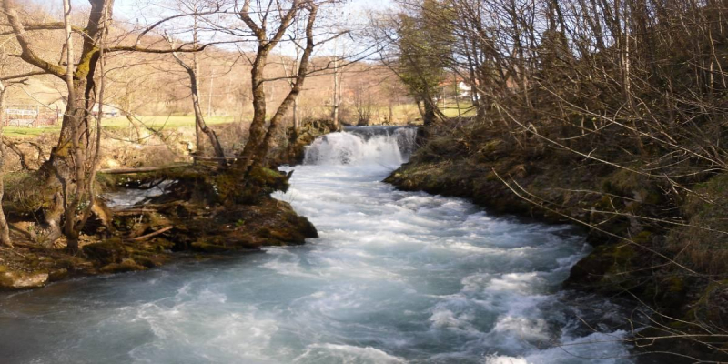
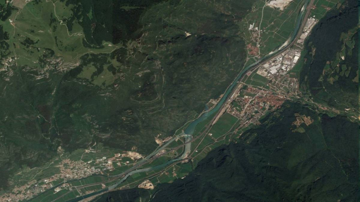
The Valbona plant is able to exploit the Ala river flows by means of an intake placed in Acque Nere, at 606 m above sea level, which supplies a 7.8 km long trapeizodal section channel. Such channel is made up of prefabricated pre-stressed reinforced concrete segments and carries through gravity (1.3% slope) a 600 l/s maximum flow up to the load tank.
The channel is placed on the right side of the valley and it is subject to rock falls events from the rocky walls above. In the past, maintenance interventions were carried out due to such events. Moreover in those sections concerned by moraine or debris deposits during extraordinary weather conditions landslide events such as mud flow – debris flow may occur, affect some channels sections. The channel breaking and the following water spill entails other and more serious landslides in the sections downstream of the damages. These landslides are very dangerous in the works lower half as there are roads and buildings which are supposed to be concerned both by the landslides and by the flow issued by the channel in an uncontrolled way.
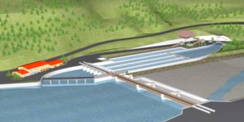
The Valbona power plant is able to produce nearly 2 MW power by exploiting a derivation concession of a maximum 600 l/s flow taken from the Ala river, with a useful difference in height of 390 m. The structure is as follows:
- Water intake on Ala river in Acque Nere, with a maximum level of the free water at 605.80 m on above sea level;
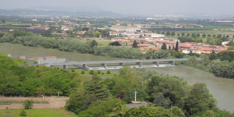
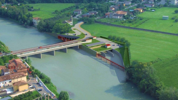
- Pre-stressed reinforced concrete trapezoidal section channel laid on level on concrete plinths cast against rock which is about 7.8 km long and constant slope equal to 1.3%; two canal bridges grant continuity on the Delle Chiese and Muravalle valleys and 3 tunnels;
- Load tank in Pozzo Basso, with 595.5 m above sea level retaining level;
- DN 500 mm 660 m long penstock to supply centrally the plant;
- DN 250 mm 660 m long penstock to discharge overflow;
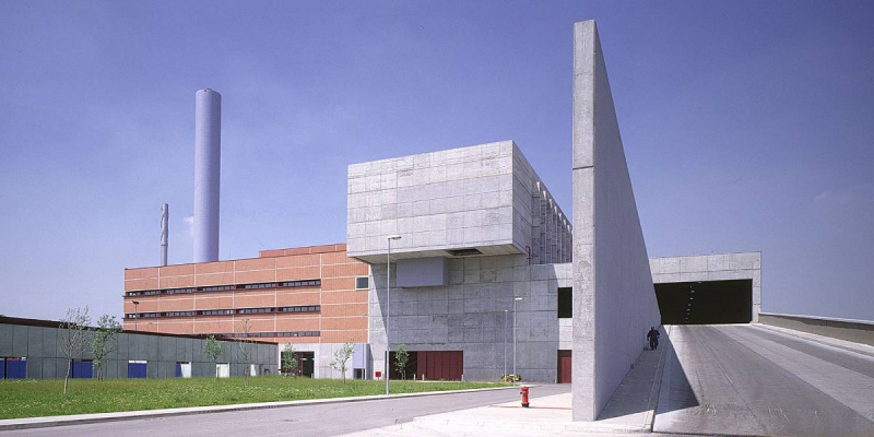
- Plant with Pelton turbin with axis at 206.20 m.
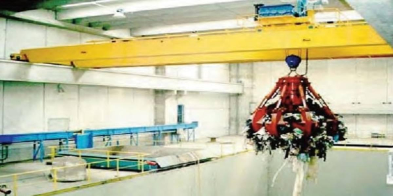
The channel is equipped with an automatic closing system which is triggered in case of break. It is made up of a gate placed at about half the length. It blocks the flow and it discharges it into a side small valley which reaches then the valley bottom and the Ala river.
The following scenarios have been studied:
- Valbona plant revamping, renovation of the intake and disposal of the channel, carrying out of a penstock on a forest/municipal road with a constant DN 800 mm diameter, and carrying out of pumping at the load tank towards the Speccheri penstock;
- Valbona plant revamping, renovation of the intake, restoration and safety of the by-pass I-II-III sections, carrying out of a by-pass tunnel of sections IV and its disposal, carrying out of pumping at the load tank towards the Speccheri penstock;
- Valbona plant revamping, renovation of the intake, restoration and safety of the by-pass I -III sections, carrying out of a by-pass tunnel of sections III – IV and their disposal, carrying out of pumping at the load tank towards the Speccheri penstock;
- Valbona plant decommissioning, renovation of the intake and disposal of the channel; carrying out of a by-pass tunnel, of a new load tank and pumping; new medium voltage supply line and a new penstock towards the Specchieri penstock;
- Valbona plant revamping, renovation of the intake and disposal of the channel; carrying out of a by-pass tunnel, of a new load tank and of a DN 800 mm penstock on forest/municipal road; carrying out of pumping at the load tank towards the Speccheri penstock.
The total project scenarios are 11.
The analyses carried out have allowed to point out as follows:
- Taking into account only the profitability parameter with reference to the investment costs seems partially misleading as the solutions A and B and the related Bis corollary solutions always have weak features which are linked to the position of the channel or of the pipe replacing it. The rock wall and the slope instability on which the channel or the new pipe is placed is not a sufficient guarantee for the need to carry out future maintenance interventions, even heavy interventions. Such interventions may increase the cost evaluation which may reach values next to the values of other solutions, mainly solutions 1 and 2;
- The final solution to be adopted must be chosen by taking into account not only the reference economic parameters but all the comparison parameters elements indicated above;
- Foreseeing tunnels instead of transfer pipes do not entail significant positive effects as the reasonably eligible tunnels dimensions in the ronchi valley do not allow more than daily adjustments and it significantly reduces the positive effect of a possible accumulation.
Client
AGSM of Verona – Veneto Region
Location
Ala di Trento (TN), Italy
Services
Preliminary and Final Design