")
Ports and Waterways Industrial and commercial ports
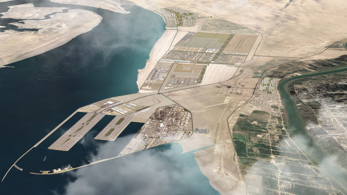
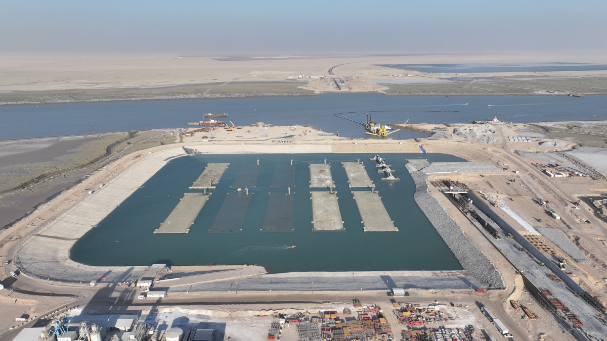
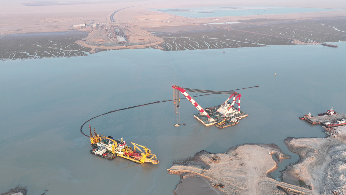
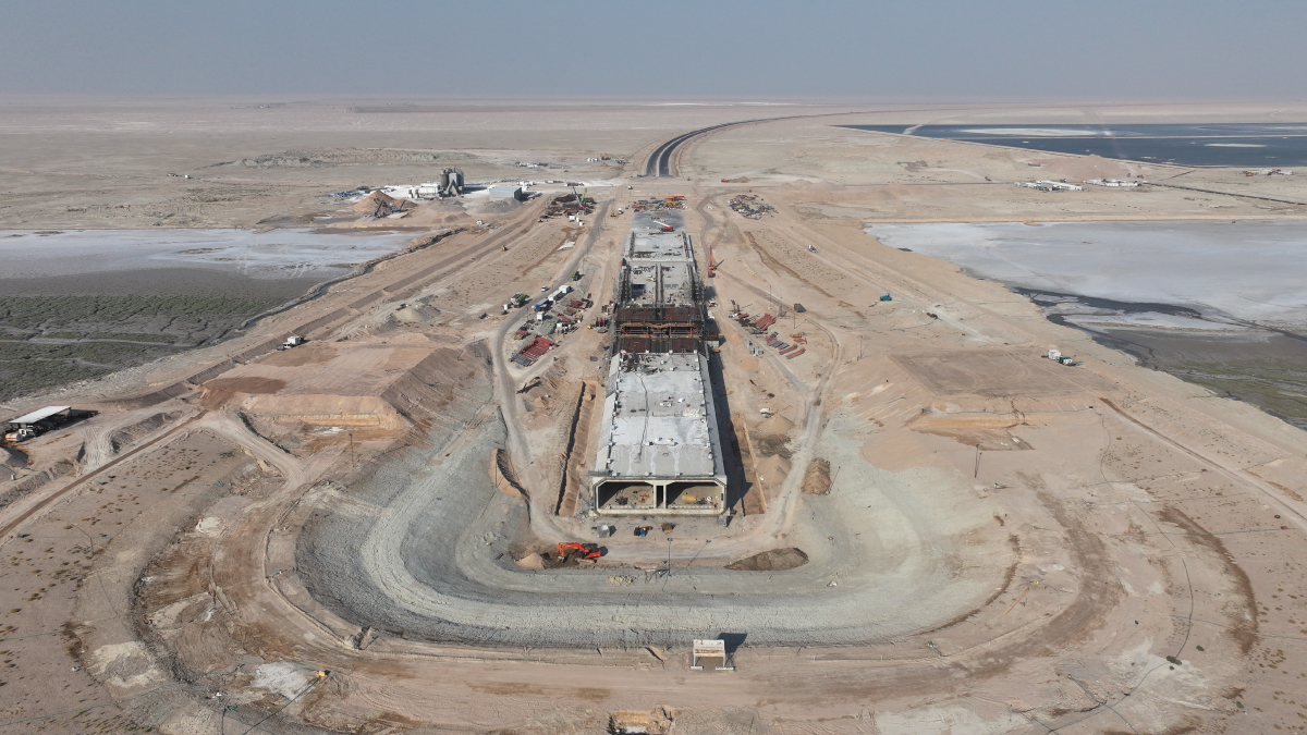
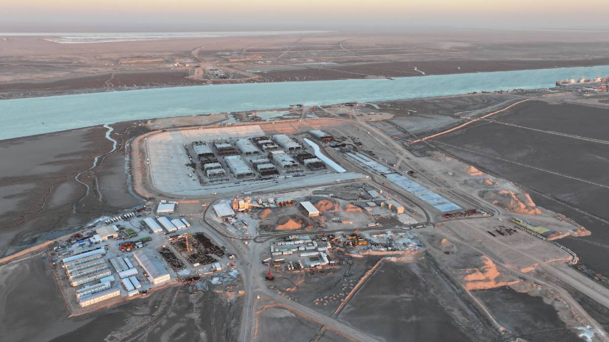
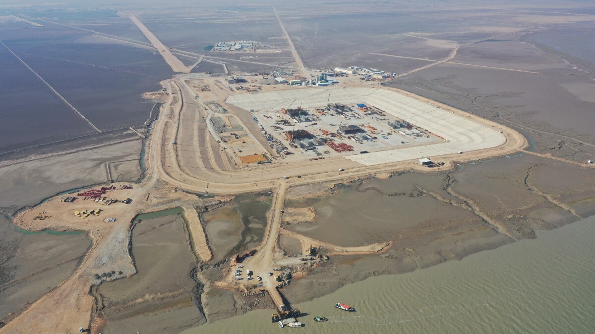
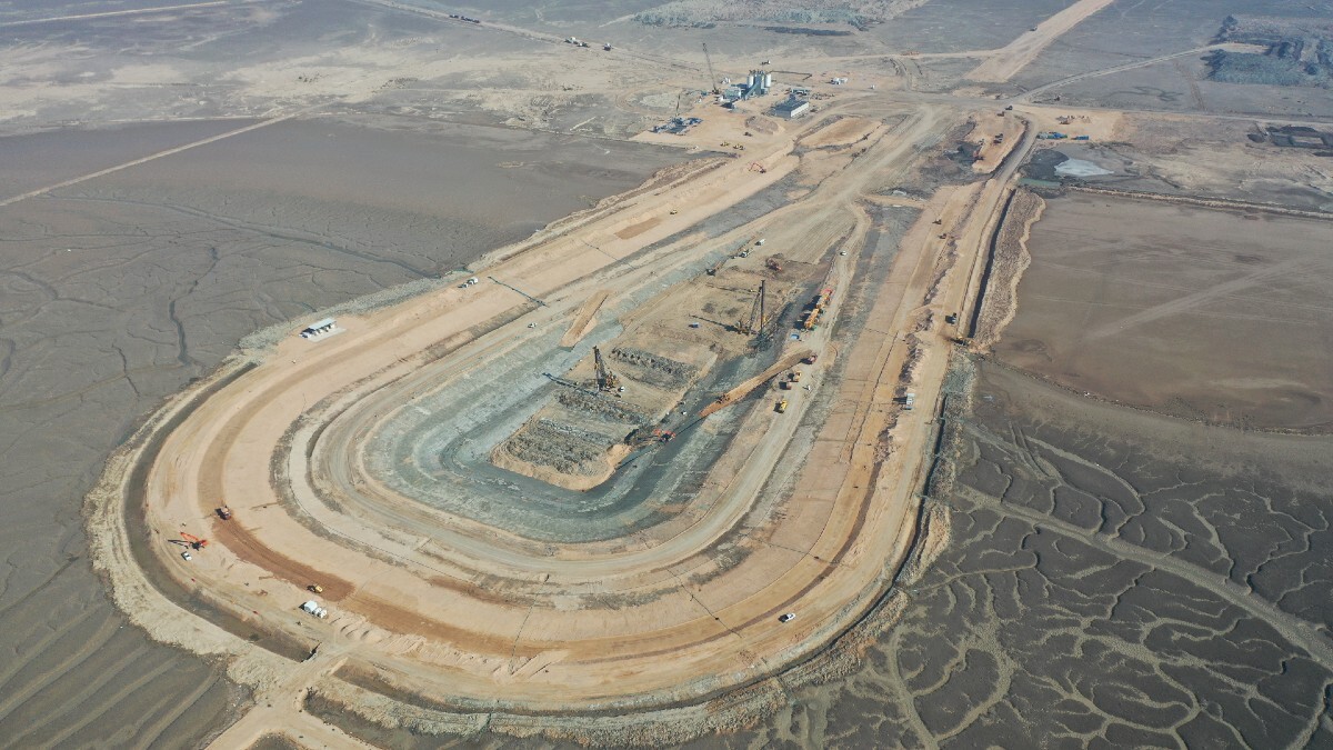
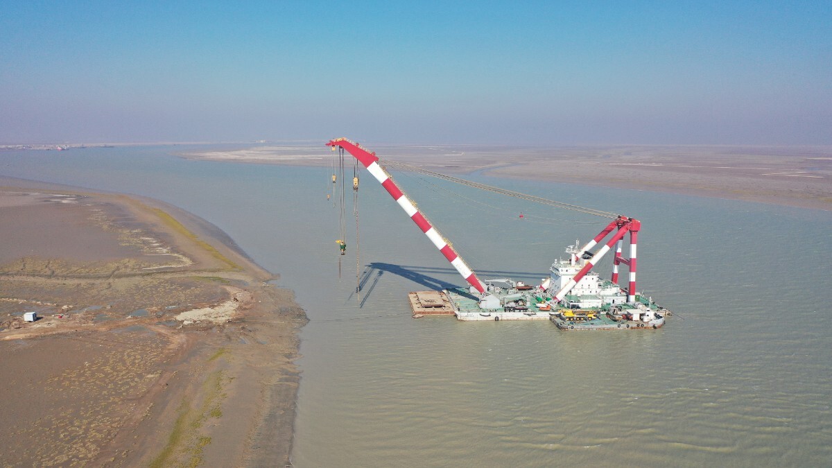
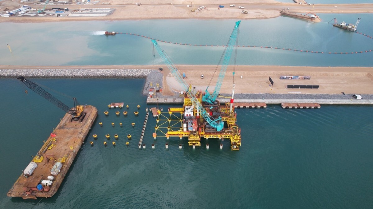
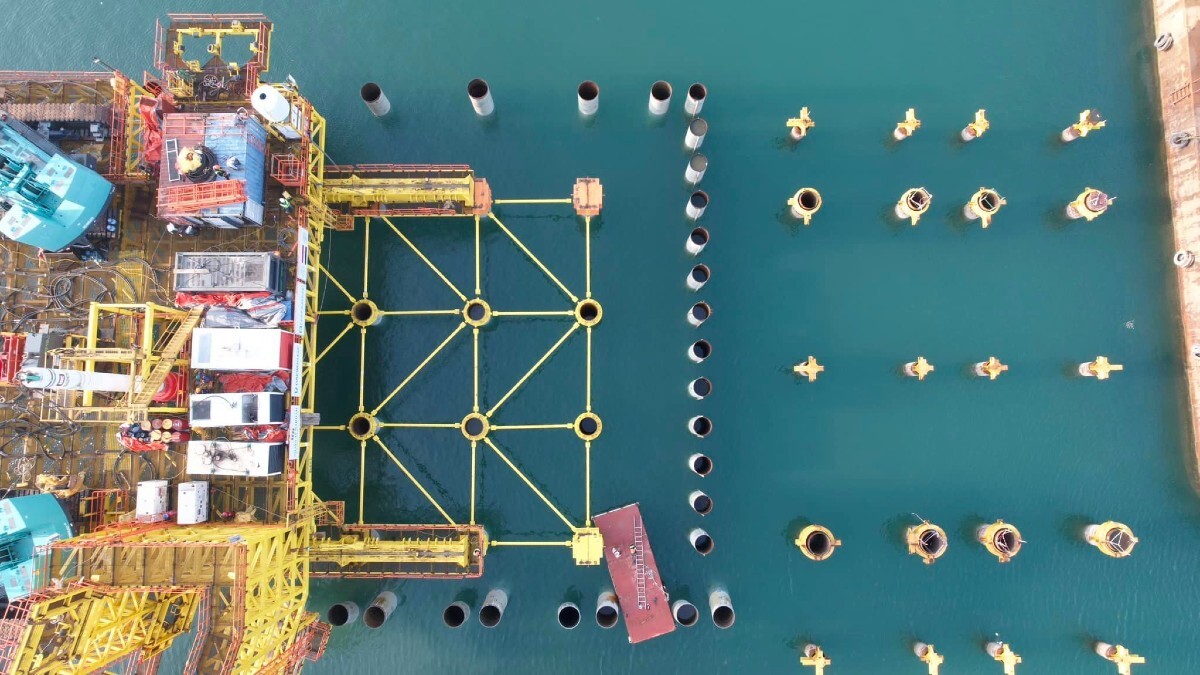
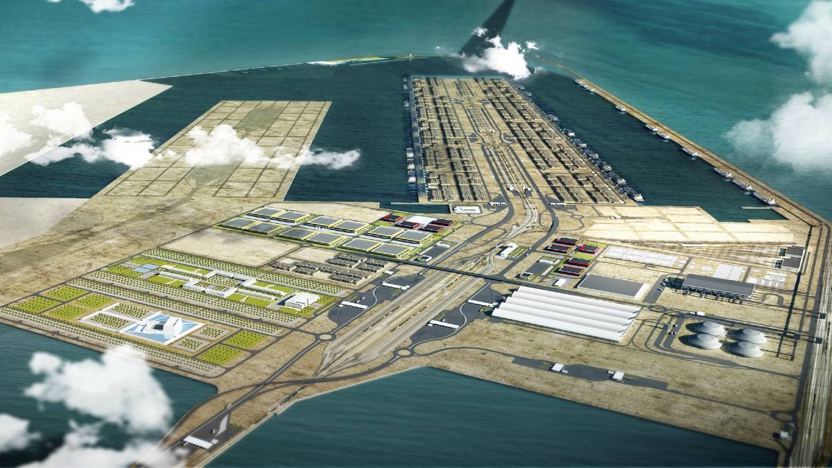
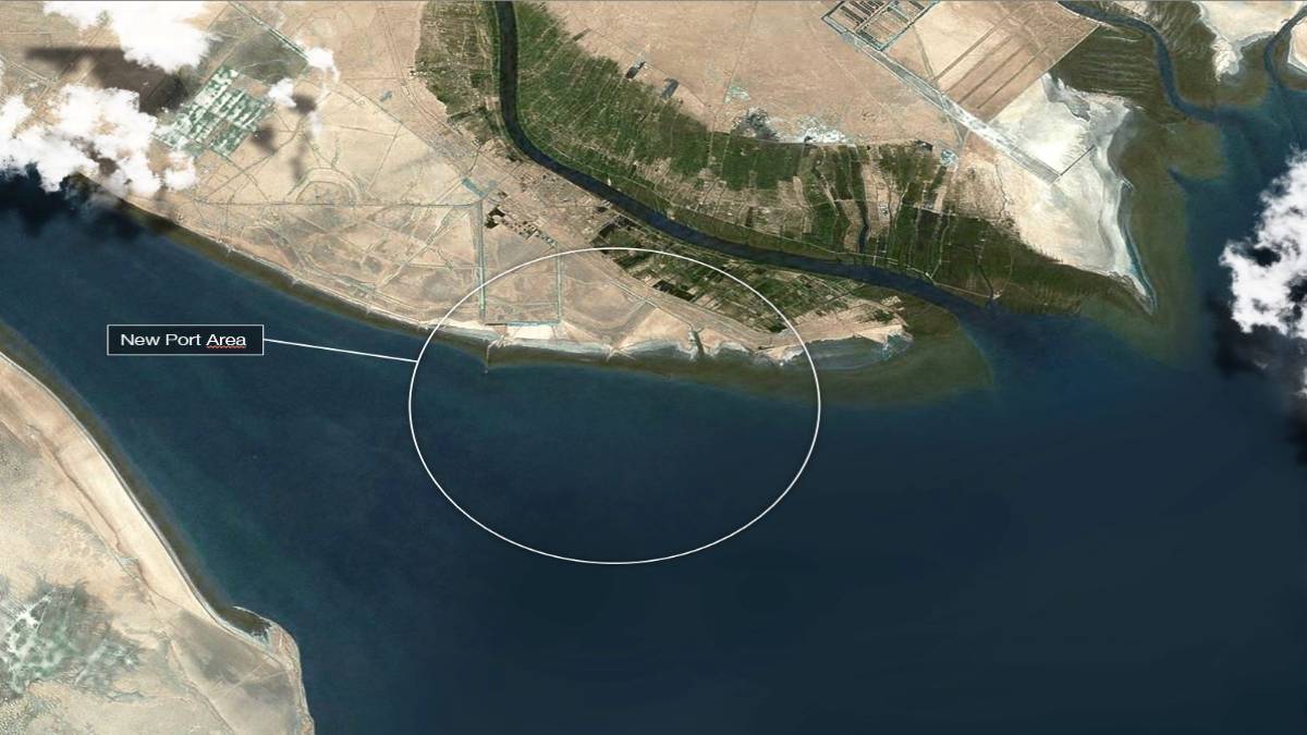
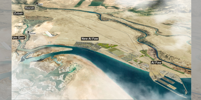
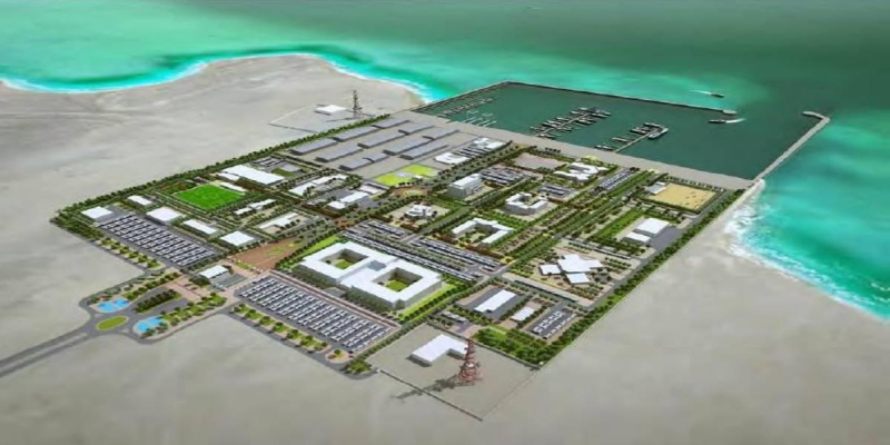
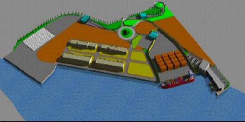
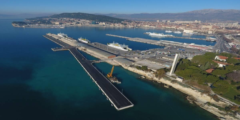
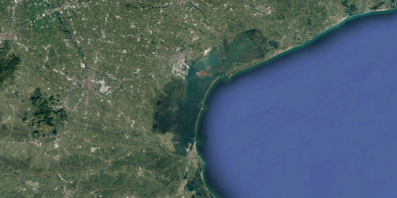
Design services and works supervision for the Al Faw Grand Port (Iraq)
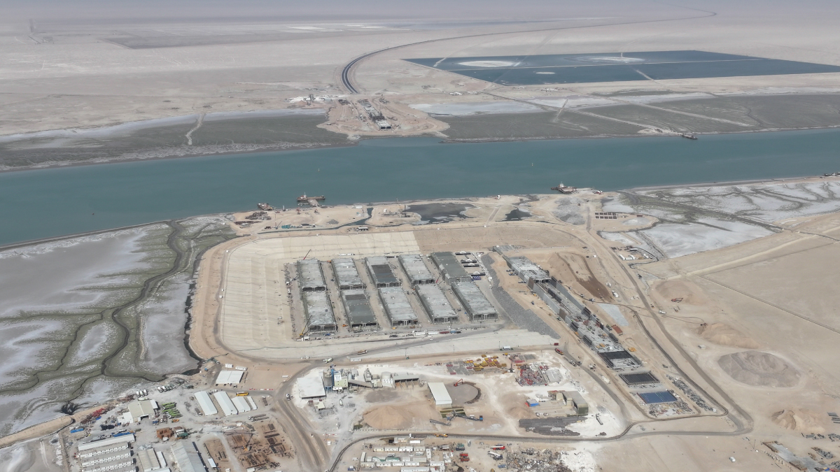
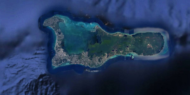
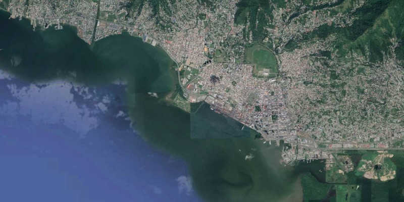
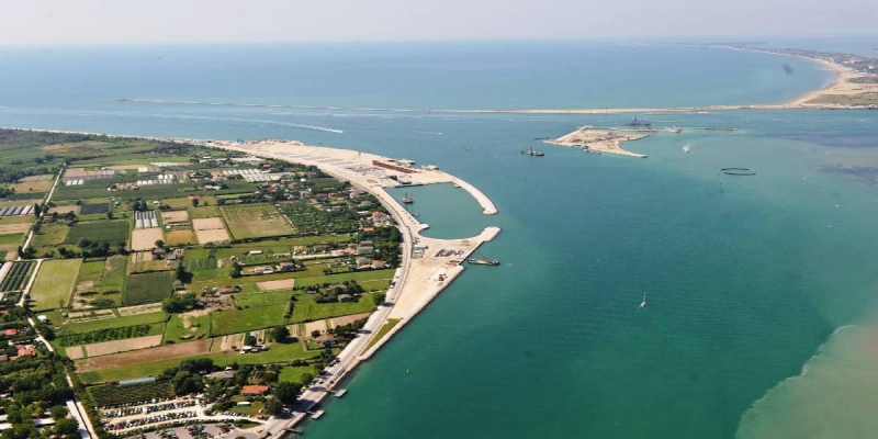
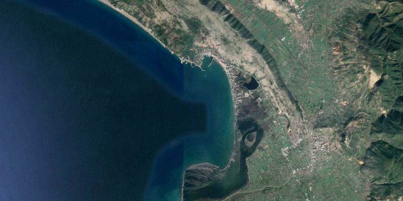
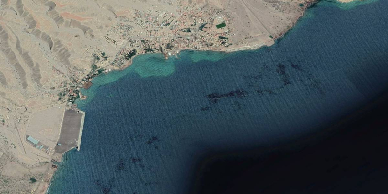
The Al Faw Grand Port will be located along the Kawr Abdallah Channel, near the Shatt Al Arab mouth, in Iraq.
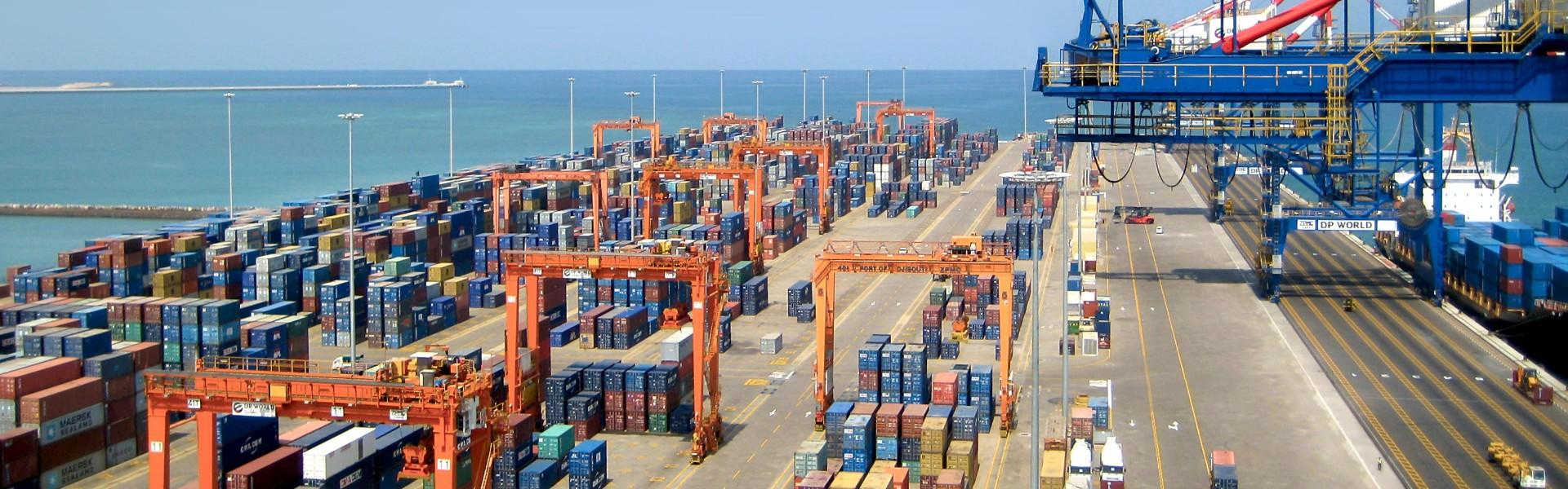
The new port is designed in order to move about 36 million tons of containerized freight (4 million of TEU) and about 22 million tons of dry bulk by 2028, to be increased respectively to 7.5 million of TEU and 33 million of tons respectively by 2038.
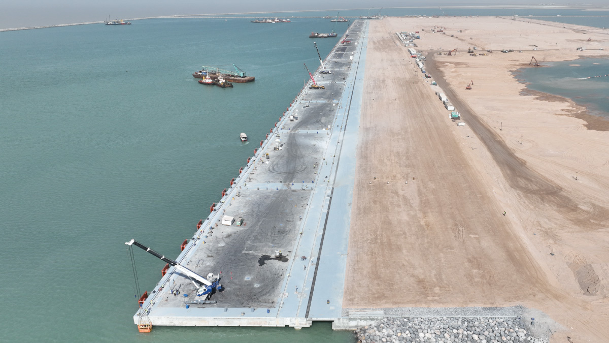
The depth of the quays ( -18.0/-18.5 m) will allow the operation of the new generation of container ships. The special quays for the operation of container ships will be 7,000 m long (about 20 berths). The quays specialized in moving dry bulk will be 3,500 m long (about 12 berths).
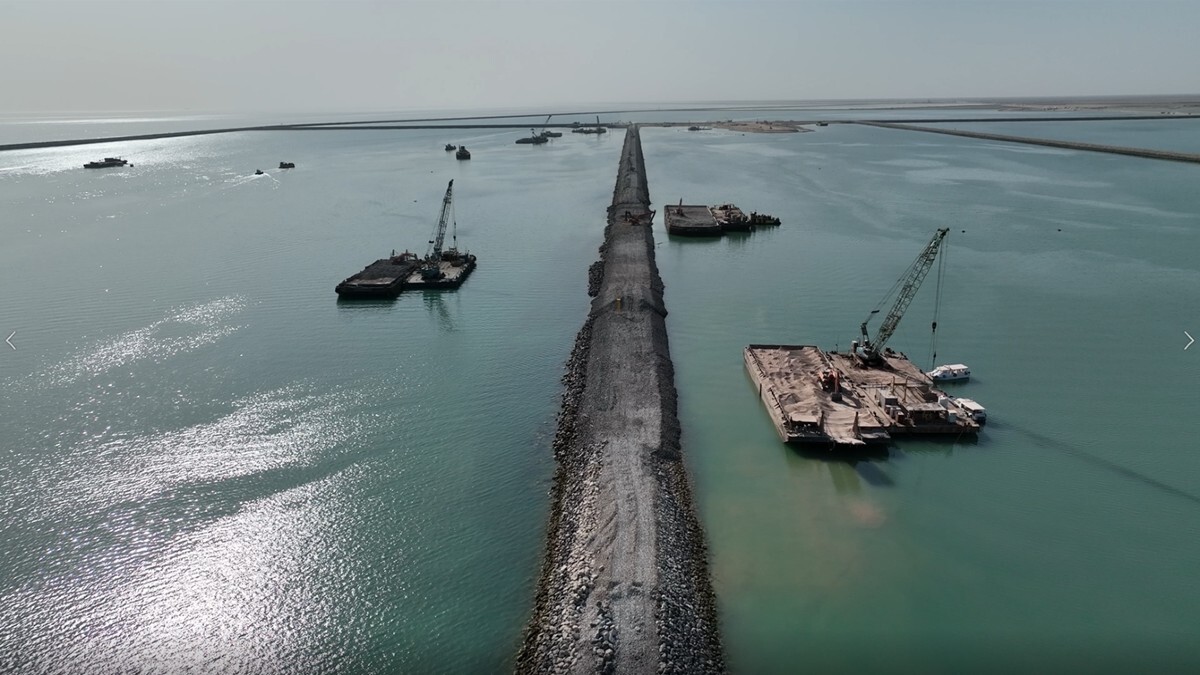
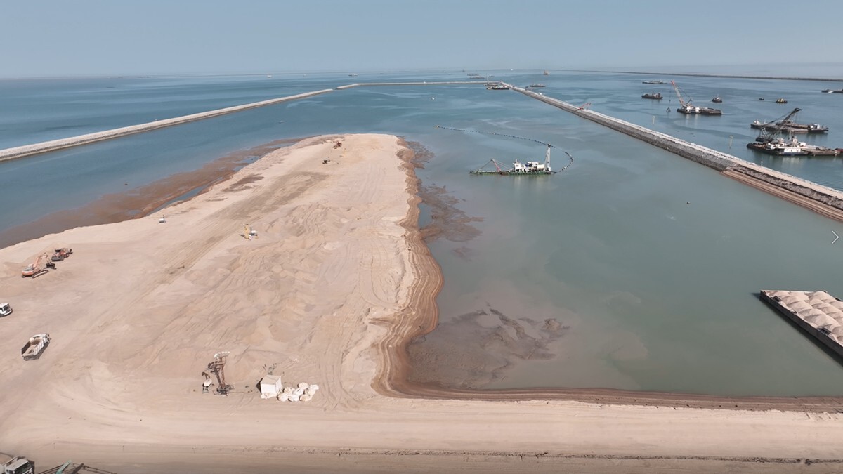
A dredged channel 400 m wide and 24 km long will connect the new port to the deep water; dredged volumes will be approximately 60.000.000 m3 for the navigation channel and 82.000.000 m3 for the port basins, protected by rubble mound breakwaters approximately 15 km long.
The project includes 2.000.000 m2 of yard for terminal container stacking, 600.000 m2 for dry bulk yards and 1.000.000 m2 of land yard for buildings and warehouses 200.000 m3 of silos for wheat.
A double lane road (2.000-3.000 commercial vehicles during peak hours) and a double track railway (80-90 couples of train/day) will connect the new port to the existing transport network.
Description of the activities:
The port layout and position have been optimised, considering the interferences with other projects under execution in the area, the possible effects on the hydrodynamics and morphology of the site, and navigational aspects. The activities incuded the review of the findigns of the Feasibility Study carried out by the Consortium CIITI completed on 2008 considering the updated information available on the existing traffic and the future demand in the country, in terms of roads, railways and ports.
The master plan of the port was developed in consideration of quays and yard extension, quay and channel depth, equipment, buildings, etc., technical requirements discussed with the Client, and also considering the results of specialist technical studies, geotechnical and hydrodynamic in particular.
The facilities needed for the port to be operative at the first stage of construction (2028) were designed at the FEED (Front End Engineering Design) level and to be sufficient to prepare the design and construction tender documents to be implemented under a FIDIC Yellow Book contract, to obtain comparable offers and to award the contract. The following facilities were dsigned at the level of FEED:
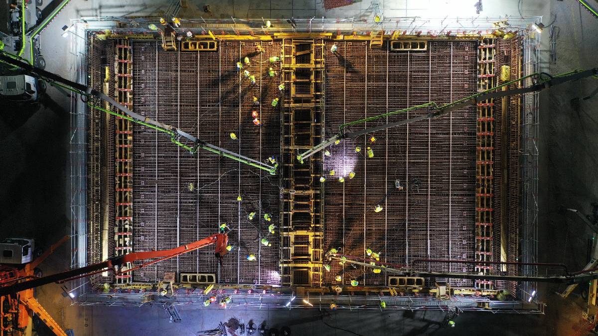
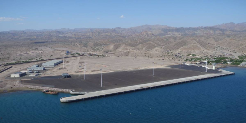
East Breakwater:
- rubble mound breakwater, approximately 8,000m in length, extending from the shoreline to approximately -6.5m msl,
- 4 hectares site bounded by peripheral breakwaters and filled with granular materials;
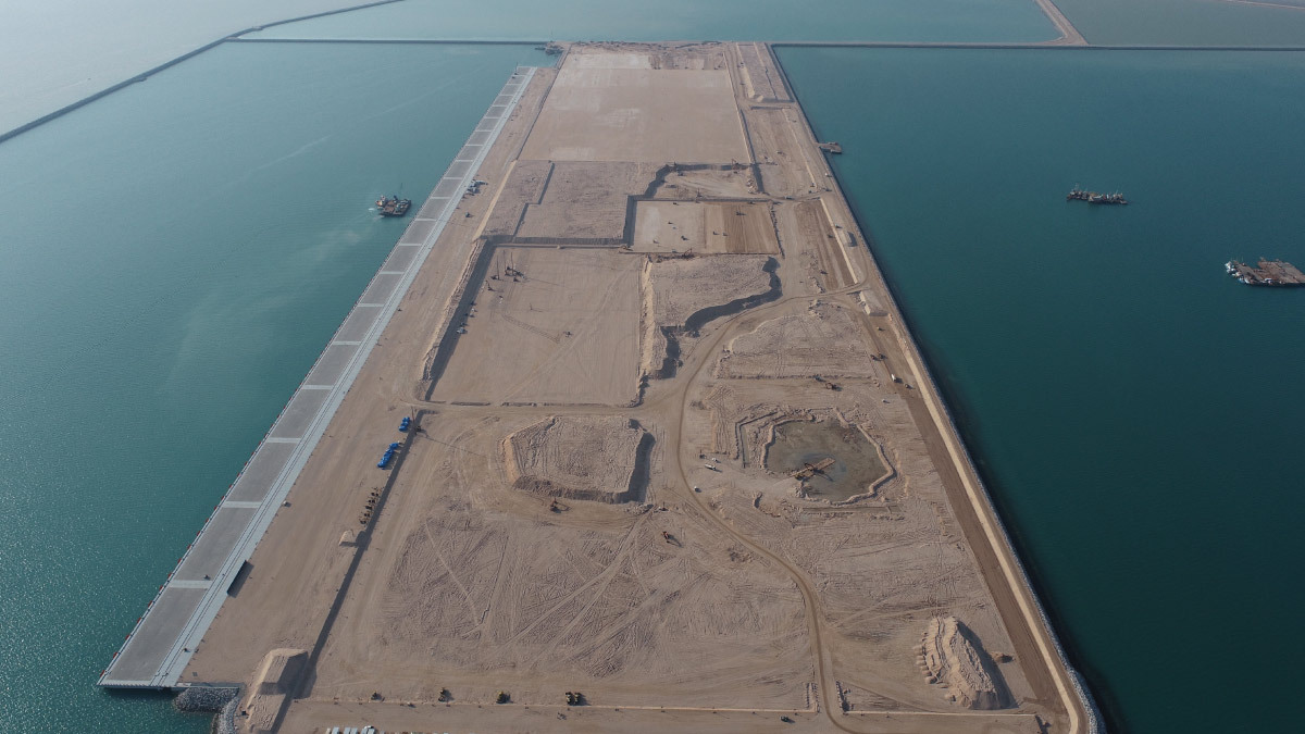
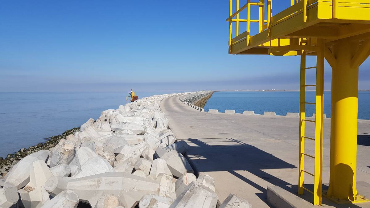
West Breakwater
- Rubble mound breakwater with concrete crown wall, approximately 13,900m in length, extending from the shoreline to approximately -9.00m msl,
- secondary rubble mound breakwater with concrete crown wall, approximately 1,650m in length, diverging from the main breakwater at approximately -9.00m msl;
Marine Infrastructures
- dredging of the port basins and of the approach navigation channel totaling an approximate volume of 95 million m3
- filling works for the creation of a 600m wide by 1750m long site for the Container Terminal, connected to another large reclamation area serving as a Container stacking yard complete with accommodation buildings, warehouses and other various facilities for the Port, made by treated dredgined material
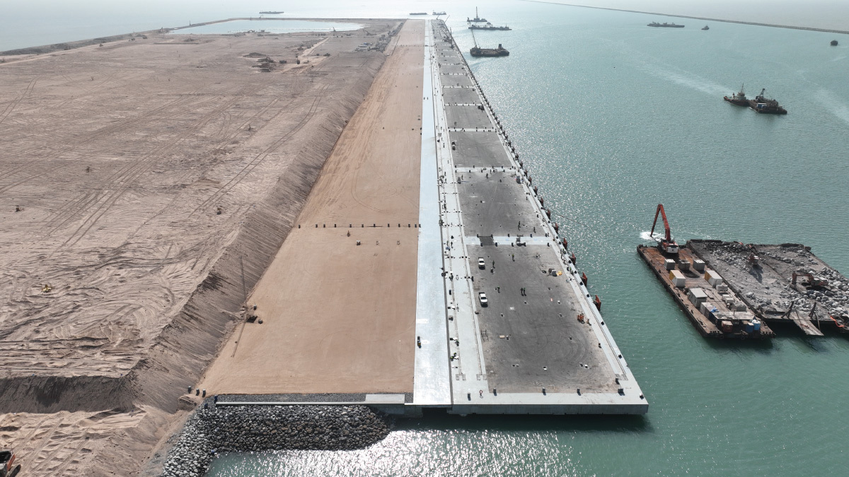
- rock revetments of the reclaimed port embankments consisting of sloping rock protection, approximately 13.2km long,
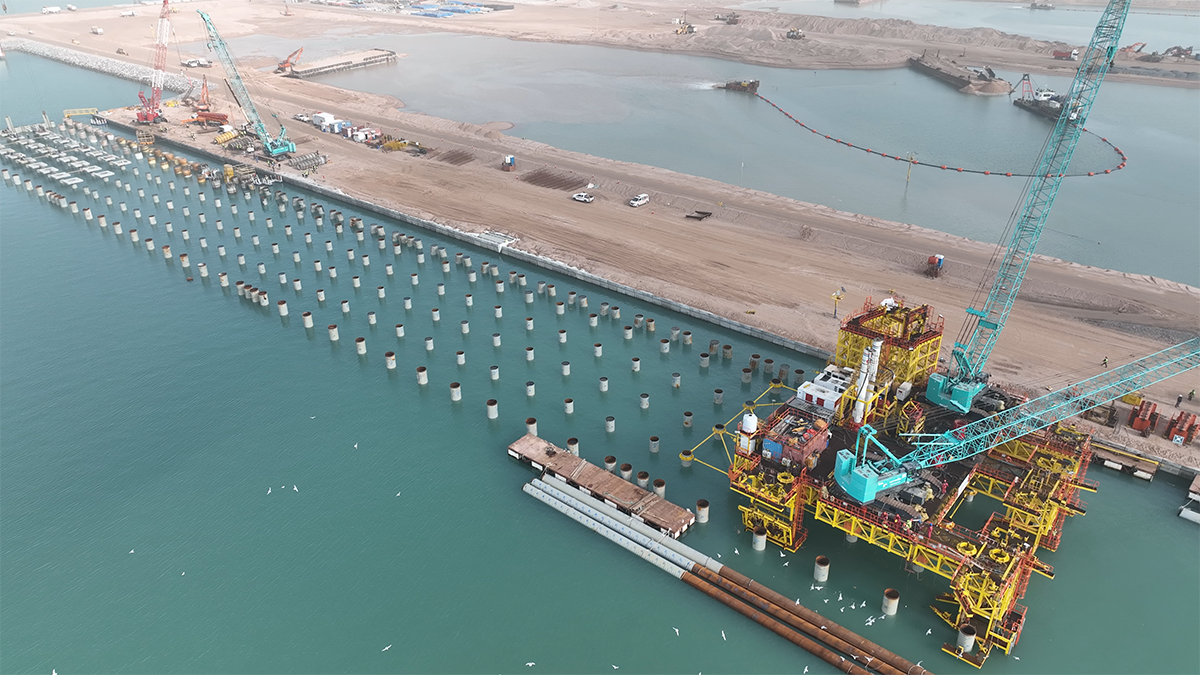
- a 1,750m long quay structure for the Container Terminal with watrer depth at -19.50m msl,
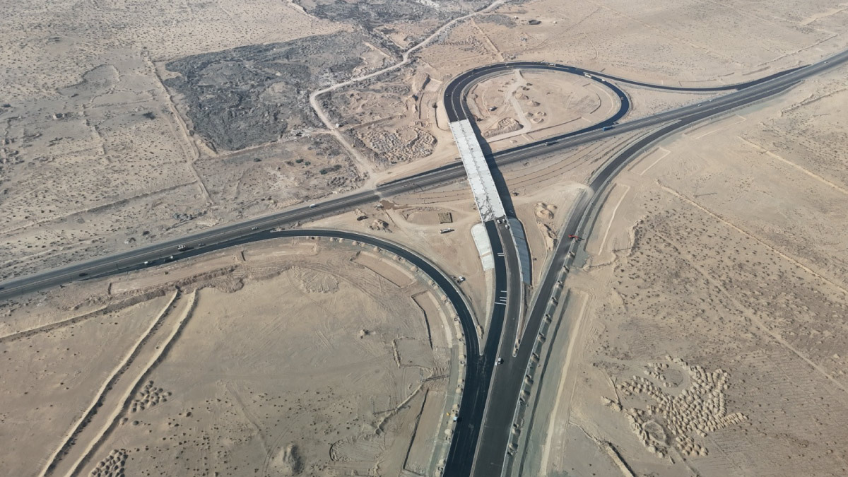
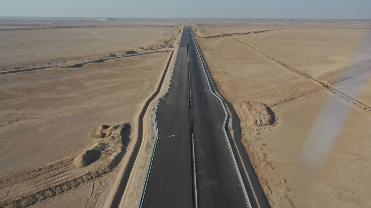
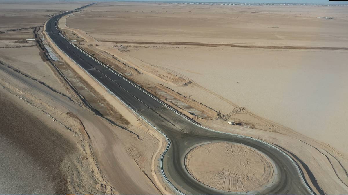
- external road network, with an extension of approximtaley 22 km,
- internal road network (serving the port loading area) with a total length of approximately 35km,
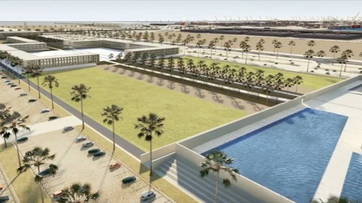
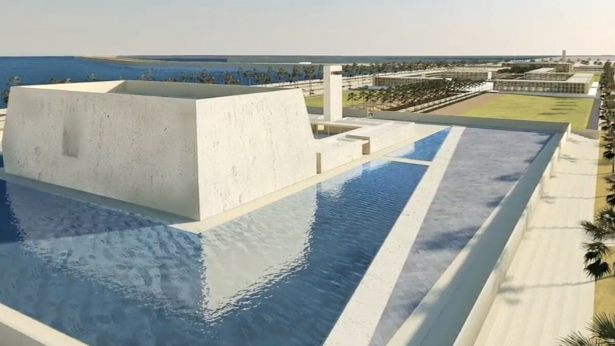
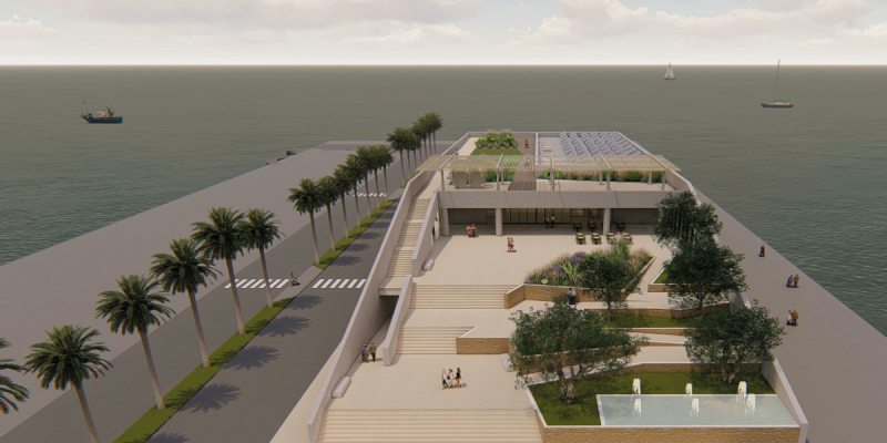
- Port Administration Building, with a gross surface area of approximately 1,260m² and related external areas of about 3,600m².
Land Infrastructures :
- N.17 buildings with a total gross surface of 63,777 m² as following listed:
- N. 44 minor buildings, n. 34 for equipment, n. 10 for railway
- N.7 shelters with a total surface of 13,498 m²
- Railway system, consisting of 6.8 km connecting the port with the boundary limits , and 4.7 km long up to the end of the Container Terminal area passing through the Reception/Departure sidings, including train and rail maintenance line, signaling system architecture and the telecommunication system;
- Fuel storage system for handling fuel oil, gasoline, marine gasoil and gasoil
- Bunkering terminal
- Power station composed by N. 2x115 MW gas turbines, fed by fuel oil
- Power distribution system consisting of a first 33 kV level for main distribution system, a secondary 6.3 kV level to supply main loads (portainers, transtainers, electrical motors above 300 kW), and a third 0.4 kV level to feed lower loads.
- Lighting system for the Container Terminal made by 35 m light towers with motorized mobile crown with 12 LED lamps, 420 W power each.
- Lighting system for the reception/departure sidings and the administration building parking with 20 m light towers with fixed crowns, equipped with 6 LED lamps, 170 W power each.
- Hazardous area lighting system consisting in metal masts with a height of 12 m equipped with lighting fixtures featuring LED lamps 120W.
- Lighting system inside the buildings consisting of fixtures lighting ranging from 14 to 36 W.
- Grounding system
- Cathodic protection system
- Telecommunication and Data system
- Intrusion Detection and Access Control Data system
- CCTV system
- HVAC system installed on all the buildings
- Iron fence securing the entire port area
- Sea water intake system to provide water for the power station (1,500 m3/h) and for the desalination unit (minimum 220 m3/h, maximum 440 m3/h).
- Sea water desalination plant with a production of 120 m3/h.
- Storage system for potable water and industrial water composed by N. 1 tank with 3,000 m3 capacity for potable water and N.2 tanks with 3,000 m3 capacity for industrial water.
- Potable and industrial water distribution pipes running in the utility culverts
- Potable and industrial water distribution systems inside the buildings.
- Gravity-flow sewerage system,
- Storm Water Drainage System
- Sewage treatment plant consisting of N°1 main plant MBR system (equivalent inhabitants: n° 1500), N° 1 plant MBR system (equivalent inhabitants N° 120) N°2 oxidation plants (equivalent inhabitants: n°60 each) and N° 7 oxidation plants (equivalent inhabitants n° 15 each)
- Fire Fighting and Fire Extinguishing System
- Instruments, Control and Safety System
- VTM and PMI systems
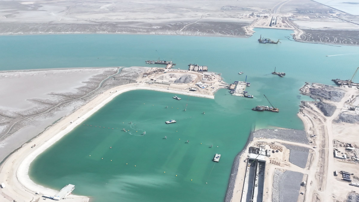
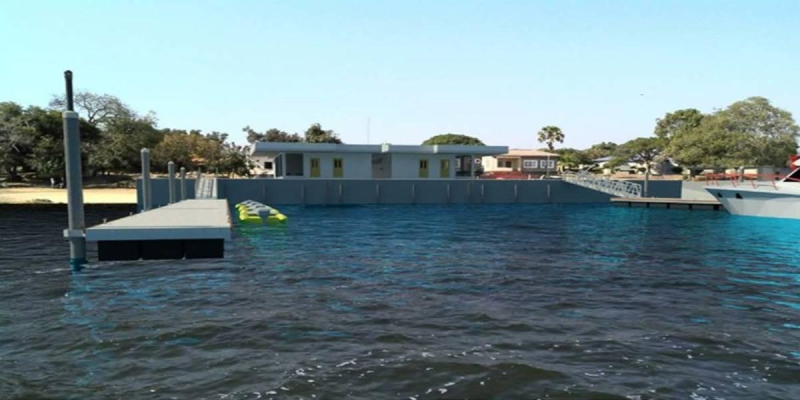
Navy Base:
- dredging of cohesive soil, clayey/silt, with minimal percentage of sand. With a total volume in the order of 2,7 million m3.;
- filling works corresponding to an extension of about 33 hectares. The filling works involve approximately 4,0 million m3;
- rock revetments, consisting of a sloping rock protection to be placed all along the north and south boundaries of the Navy Base embankment, approximately 0.7 km long
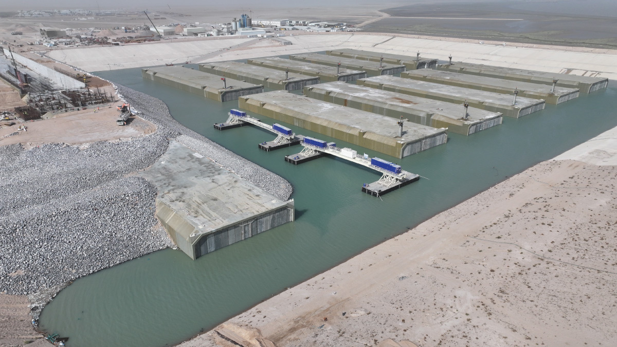
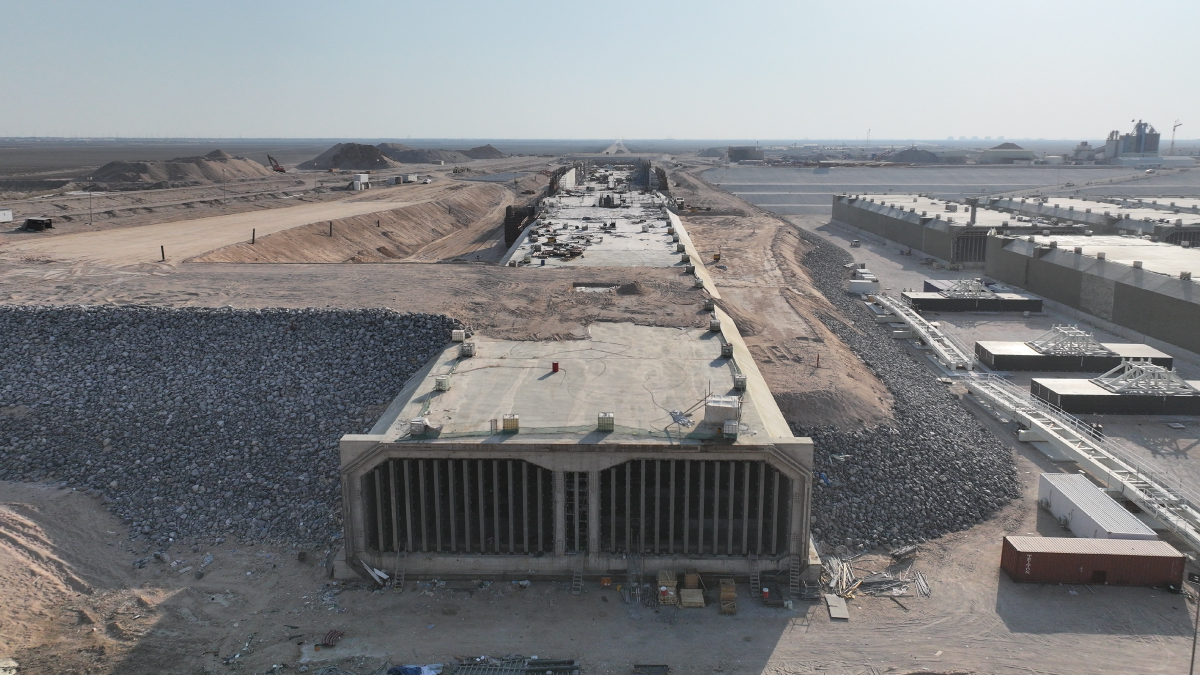
- a 1,750 m long quay for the Navy Base. The quay structures consist of precast concrete caisson, with pavement level at +4.00 m m.s.l. and sea bottom dredged at -7.50/-11.00 m m.s.l.;
- floating pontoons: n.45 modules 20m long and n.20 modules 15 m long,
- a floating breakwater 1160m long, to reduce wave agitation.
- internal roads and paving of the yard (11 hectares)
- external roads and relevant structures, including drainage, underpasses, fence and lightning (7,6 Km)
- n. 39 buildings, gross surface of 10500 m²: n.1 Control Building (Security Check Point), n.1 Utility/Mechanical Building, n.2 Tollgate cabin, N.1 Shelter, n. 23 Guard Towers, n. 1 Maintenance Wet Dock shelter, N.1 Control Room and Laboratory Building, n. 9 Electric substations;
- fuel storage and distribution/de-fuel system (n.6 different products, total storage capacity of 5.400 m3)
- reverse osmosis desalination system (production flow of 10 m3/h)
- water storage and distribution system (storage capacity 2.750 m3)
- LV/MV power system, for cold ironing and buildings (20 MVA total consumption), and n. 3 emergency diesel generators, sized in 11 MVA total
- other secondary technological systems (I&C, firefighting, security systems, lightning, sewage, HVAC, telecommunication & data, irrigation, etc)
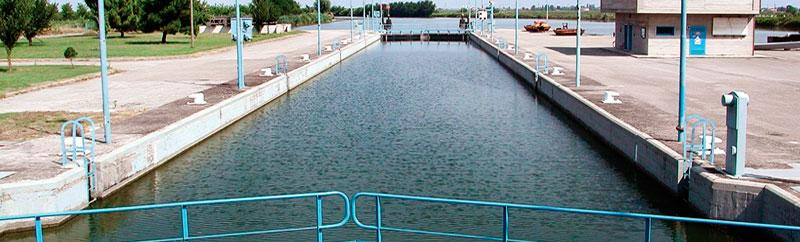
- n.1 Ship Lift (platform dimensions 20x65 m, handling a vessel of 1400 t) and n.1 Ship Transfer System (1,9 Km long railways)
- technological systems from/to Marine Terminal (Gasoil, Gasoline, I&C)
- technological systems from/to Navy Base utilities area near Tank Farm (MV power, I&C, industrial water, telecom & data);
- technological systems from/to Control Tower (industrial water, MV power, telecom & data)
Oil Terminal:
- N. 1 Tank Farm with 11 product tanks, divided as follows:
- Gasoil - n° 3 x 38,000 m3 each;
- Gasoline - n° 3 x 38,000 m3 each;
- Kerosene - n° 2 x 25,000 m3 each;
- ATK - n° 2 x 25,000 m3 each;
- Bunker Oil for tankers - n° 1 x 10,000 m3.
- all loading and unloading facilities, export booster pumps, metering stations, service buildings and all related utilities.
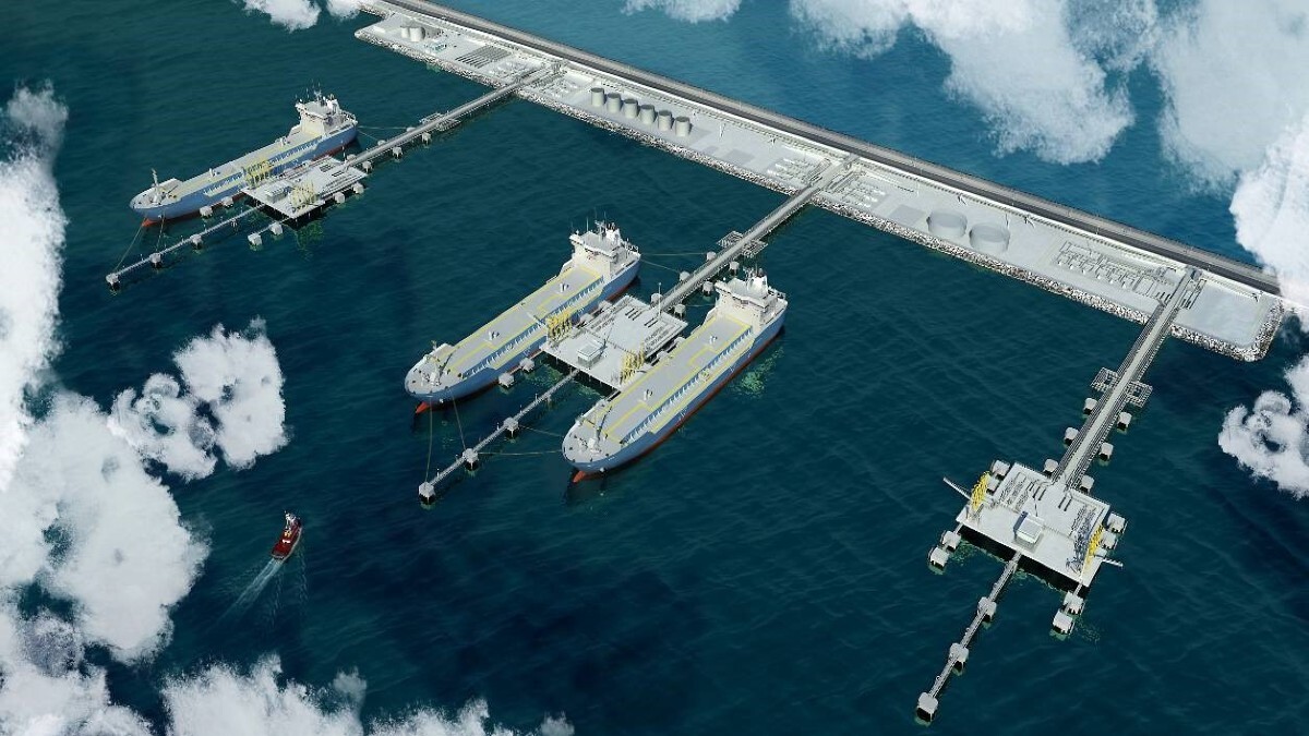
- N. 1 Marine Terminal with three independent jetties on steel piles:
- n° 2 jetties shared between Gasoil and Gasoline (tankers up to 60,000 DWT);
- n° 1 jetty shared between Kerosene and ATK (tankers up to 30,000 DWT).
- Each berth provided with three fully-balanced loading/unloading arms for the products. Additionally each berth will have a dedicated unloading arm for de-ballasting water, and a loading arm for bunkering.
- Connection pipelines between the Tank Farm and the Marine Terminal
The port will be implemented in different stages. At the date 2 stages of construction have been awarded the East Breakwater/Staging Pier and the West Breakwater.
Technital is in charge of assistance during the tender stage until the negotiation and signature of the contract for design & build and is in charge of the supervision of works.
Client
Ministry of Transportation of the Republic of Iraq
Location
Al Faw, Iraq
Services
Master Plan, Detailed Design, Tender Documents, Assistance during Tender; Works Supervision, PMC
Cost of works
Euro 11.7 billion